-
Notifications
You must be signed in to change notification settings - Fork 36
Light and Shadow
In FUSEE we are capable to place various light sources in the scene by using LightComponent. They should be one of the LightTypes.
Other useful properties of the LightComponent are Active, Color and Strength.
As described above, some light types need a position and/or a direction to light the scene in the intended way. Those are not properties of the LightComponent itself, but calculated based on the TransformComponent, associated with the light. This enables us to use one LightComponent multiple times in the scene graph.
The position of the light in world space -- if used in a Scene Graph, also relative to the parent node -- is simply set by the translation property of the TransformComponent.
The default direction of a light is the positive z-axis of the world space. To change it, we need to add a rotation to the TransformComponent. For example: if we set a rotation of 90 degree around the positive x-axis, the lights direction will become equal to the negative y axis.
Exemplary setup of a spot light:
var blueSpotLightComponent = new LightComponent()
{
    Type = LightType.Spot,
    Active = true,
    Color = new float4(0, 0, 1, 1),
    MaxDistance = 100,
    OuterConeAngle = 25,
    InnerConeAngle = 5
};

var blueSpotLight = new SceneNodeContainer()
{
    Name = "blueLight",
    Components = new List<SceneComponentContainer>()
    {
        new TransformComponent()
        {
            Translation = new float3(-5, 10, 0),
            Rotation = new float3(M.DegreesToRadians(90), 0, 0)
        },
        blueSpotLightComponent,
    }
},💡 Note: The forward rendering pipeline supports eight light sources at the most!
Further lights will simply not be rendered.
In the deferred pipeline the number of lights is only limited by our hardware.
💡 Note: Shadow casting is only available in the deferred pipeline!
See the Deferred Rendering Page on how to use it.
FUSEE is able to render shadows for every light in the scene. For this the engine uses Shadow Mapping. In short this done as follows:
For every light source
- render a depth map (= shadow map) of the scene from the light's position. For spot and point lights this will be the position given in the TransformComponent. For parallel lights it is calculated internally.
In the lighting pass
- transform the position into light space.
- Check whether the position's z value is lesser or greater than the associated texel of the shadow map. If it is greater, this fragment lies in shadow.
For further information and OpenGL implementation details refer to this tutorial on learnopengl.com.
To enable shadow casting for a specific light, we need to set the property IsCastingShadows of the Light to true. Furthermore it may be possible to adjust the Bias of the LightComponent.
The bias can have a massive impact on the quality of the shadow.
If it is too small it can lead to incorrect self shadowing or shadow acne.
If it is to big, peter panning (the shadow isn't attached to associated object anymore) or light leaking can occur.
In the event that we do not see a shadow, but are sure that we have set all parameters of the light correctly, this may also be due to a incorrect bias. Try playing around with it to get the best results in terms of shadow quality.
We can choose the resolution of the shadow maps in the SceneRendererDeferred by setting the value of ShadowMapRes.
The higher the resolution we choose the clearer the shadow will appear, because we have a better texel to fragment assignment (step three of the short description above).
Keep in mind, that a higher resolution may have an impact on the performance of the application.
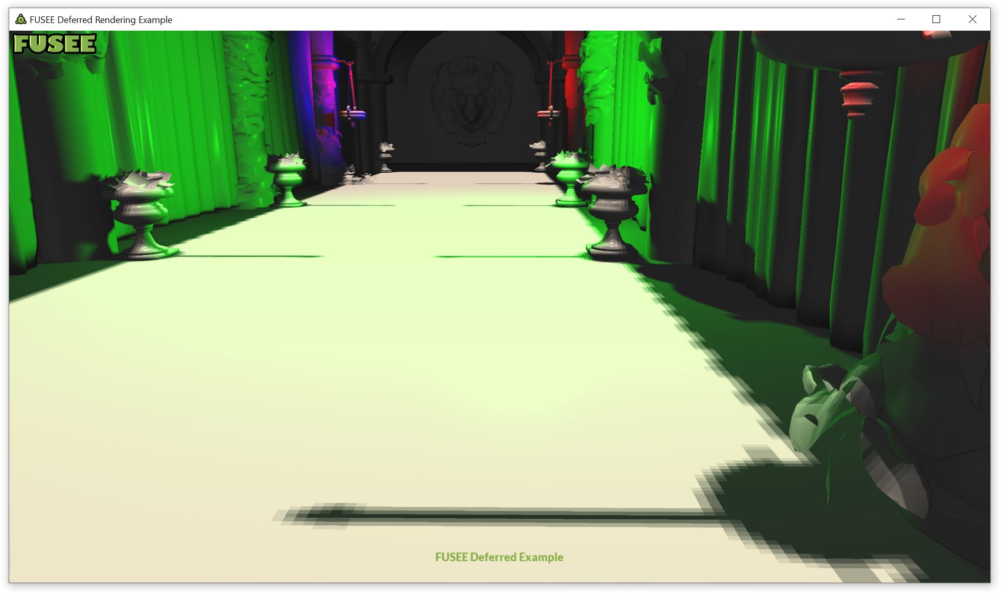
If we encounter bad quality shadows coming from parallel lights (like those seen in the picture below), it may help to increase the numberOfCascades in the SceneRendererDeferred. This will increase the number of shadow maps that are created for each parallel light. A number to great may result in performance loss.
As described above, parallel lights light the whole scene. In the basic shadow mapping algorithm we would have one shadow map with (in a worst case scenario) 512 x 512 pixel that needs to cover a big scene, maybe spanning several kilometers in world space - or at least the part of it, that is inside the viewing frustum, which can also have a big volume. This leads to shadows with a very bad quality as seen in the picture below.

We can also see, that the farther away a point is from our point of view, the less noticeable the bad quality gets. This leads to the idea of Cascaded Shadow Mapping.
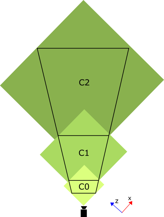
With this, the viewing frustum is split into n cascades, here given by the numberOfCascades. The algorithm used to split the frustum is Parallel-Split Shadow Maps.
For each cascade the algorithm calculates the axis aligned bounding box, which encloses the cascade. This bounding box is used as the (orthographic) viewing frustum for rendering the shadow map for this cascade. This results in shadow maps with a better texel to fragment assignment, because each shadow map only displays a subset of the scene.
The picture below shows the cascades (C0 - C2) and the bounding boxes (green).

In the lighting pass, the shader determines the correct cascade for each fragment and calculates the shadow according to the shadow map associated with this cascade. Note that it is okay if the bounding boxes intersect, as long as the shader chooses one of the shadow maps.
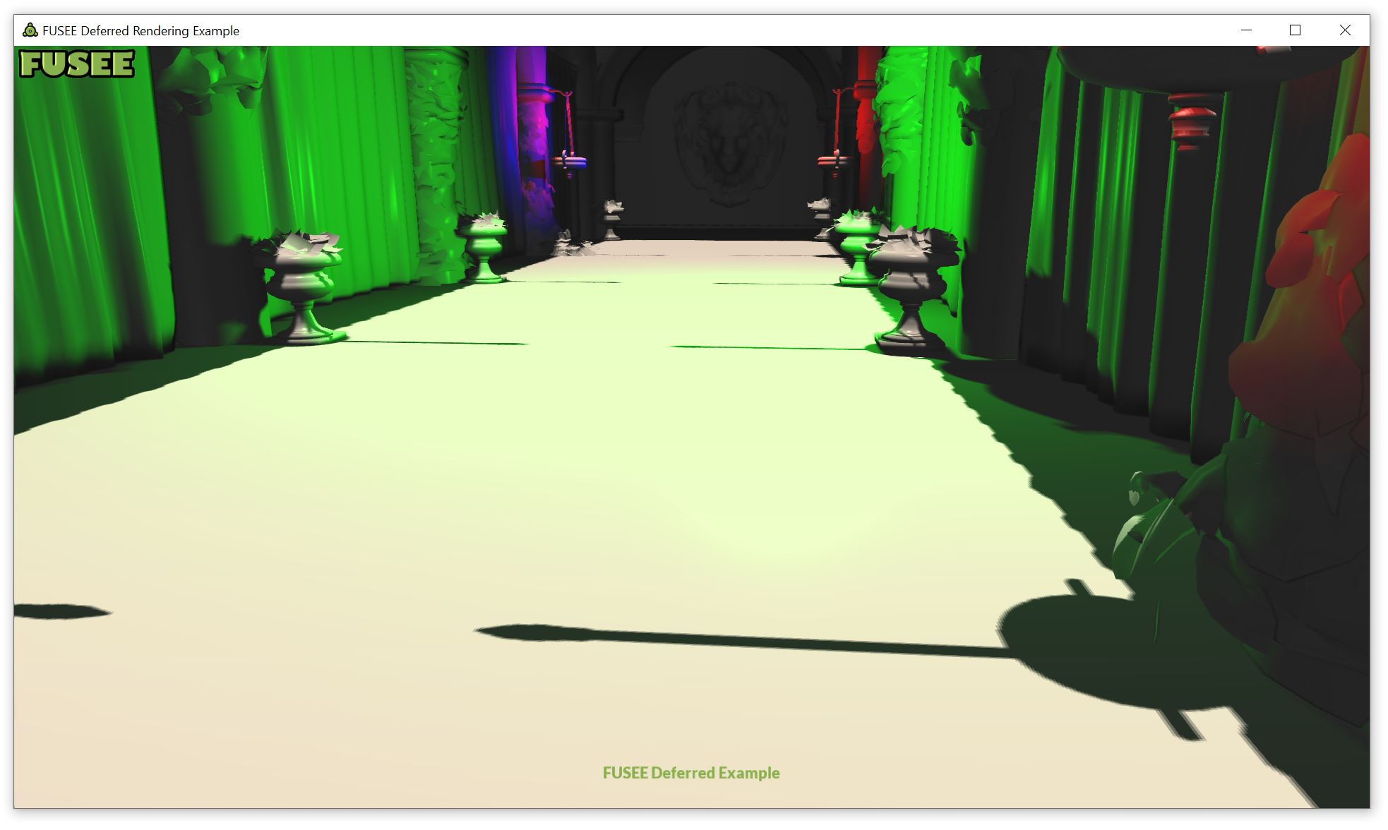
In the case shown above the quality is improved significantly by using three cascades:

- Using FUSEE
- Tutorials
- Examples
- In-Depth Topics
- Input and Input Devices
- The Rendering Pipeline
- Render Layer
- Camera
- Textures
- FUSEE Exporter Blender Add on
- Assets
- Lighting & Materials
- Serialization and protobuf-net
- ImGui
- Blazor/WebAssembly
- Miscellaneous
- Developing FUSEE